Documenting an interesting 3D modeling and rendering project: a rainbow infinity symbol composed of a Möbius strip.
⚓ Goal
I want to model an infinity symbol made of Möbius strips, with these properties:
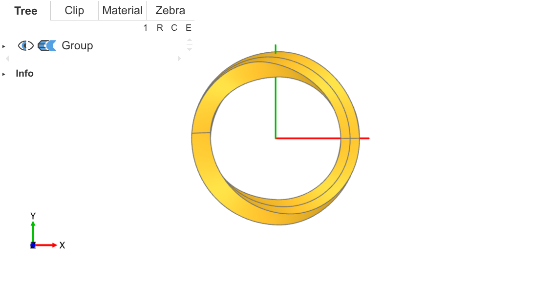
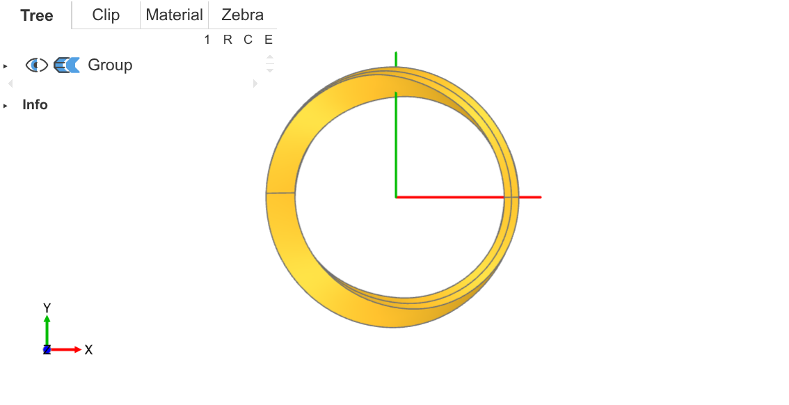
- A perfect circle in the top view.
- A perfect infinity symbol ($\infty$) shape in the front, back, and both side views.
Why a perfect circle? Because this allows me to use radially hue-gradient colored lights starting from the origin to illuminate the object, rendering a uniformly shimmering rainbow infinity symbol.

⚓ Modeling
I used Python's build123d library for modeling. This library is a CAD modeling library based on the Open CASCADE kernel, allowing design of complex 3D models in code.
I made many mistakes along the way; modeling an irregular Möbius strip is actually not easy. This article will directly present a correct modeling path, occasionally mentioning the errors I made earlier.
⚓ Preparation
First, import build123d, and the ocp_vscode library for debugging, then define some parameters, the meanings of these parameters will be mentioned later.
from build123d import *
from ocp_vscode import *
import math

class Config:
    def __init__(self):
        self.radius = 20.0
        self.max_height = self.radius
        self.width = 5.0
        self.thickness = self.width
        self.segments = 360

cfg = Config()
⚓ Main Path
I model the main path first, which is the centerline of the entire object. This path needs to meet the two properties mentioned earlier: a perfect circle in the top view, and looking like an infinity symbol in the front/back/side views.
⚓ First Quadrant
Placing the center of this main path circle at the origin, a simple thought reveals that this main path is similar in all four quadrants. So, I only need to model the path in the first quadrant, then use mirroring&rotation operations to get the complete path.
def build_q1_line():
q1_xy = CenterArc((0, 0), cfg.radius, 0, 90)
wall_face = sweep(q1_xy, Line((0, 0, 0), (0, 0, cfg.max_height)))
q1_plane = Plane.XY * Pos(cfg.radius / 2, cfg.radius / 2) * Rotation(Z=-45) * Rotation(X=45)
splitted = split(wall_face, bisect_by=q1_plane, keep=Keep.BOTH)
edges_diff = splitted.edges() - wall_face.edges()
assert len(edges_diff) == 1
return edges_diff[0]
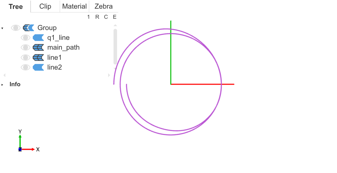
q1_line = build_q1_line()Let's go through it step by step:
-
First, I created a quarter-circle arc
q1_xyin the first quadrant, which is the projection of the main path on the XY plane. Then I used sweep to lift the arc into a facewall_face.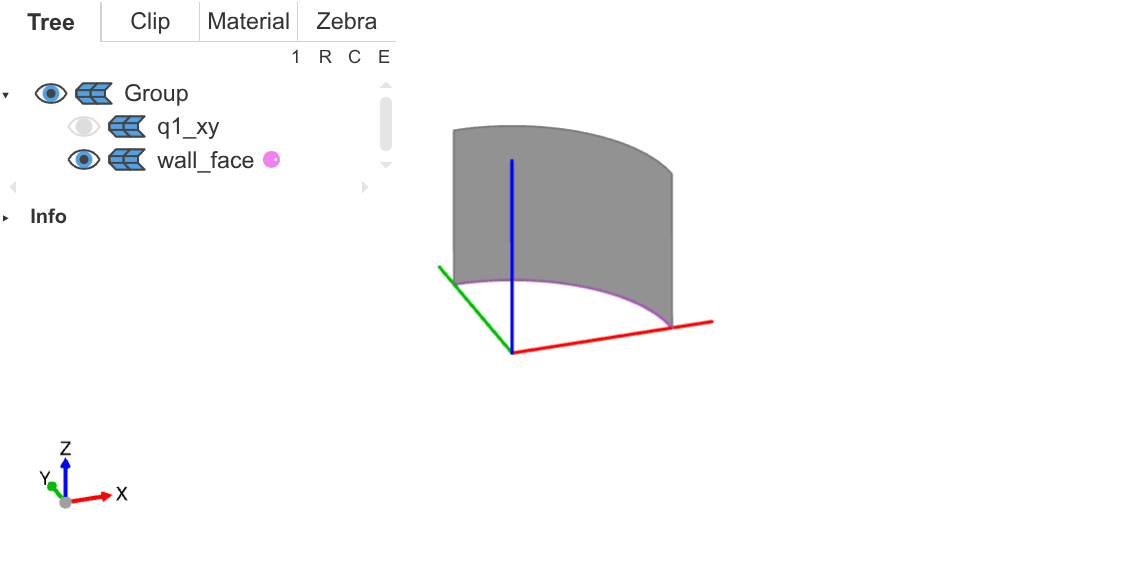
First quadrant arc face -
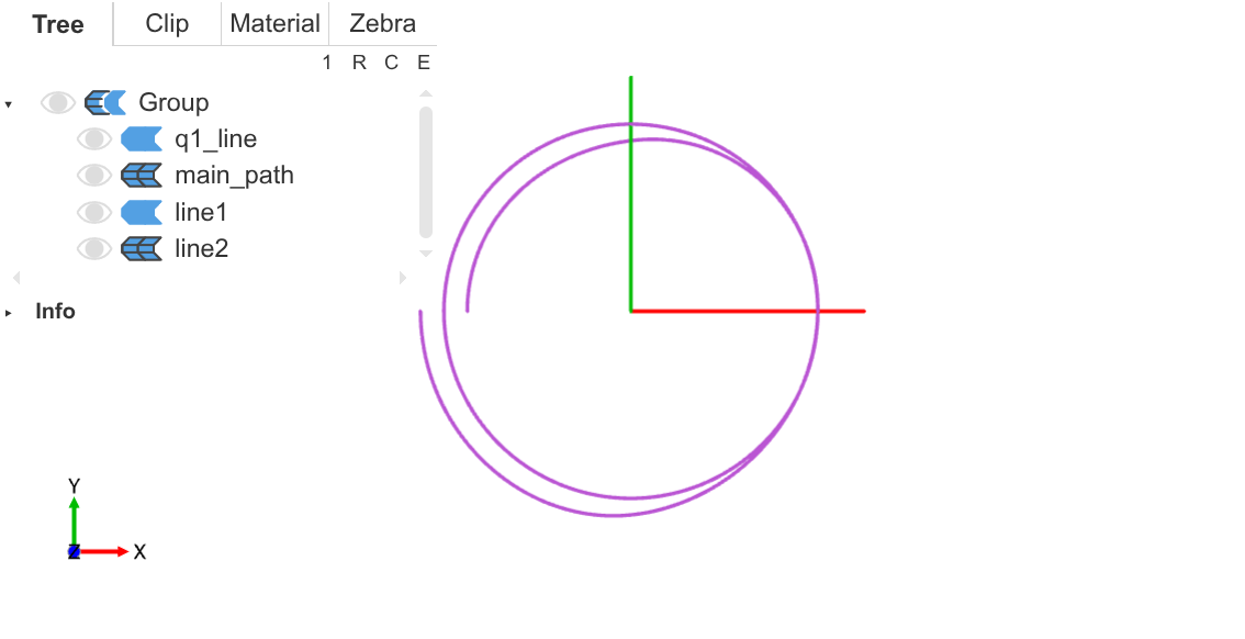
Second, I constructed a plane tilted 45 degrees upward and used it to cut the previous face. This plane intersects the two endpoints of the first quadrant arc. Therefore, after cutting, the endpoints of the cutting line will exactly fall on the coordinate axes.
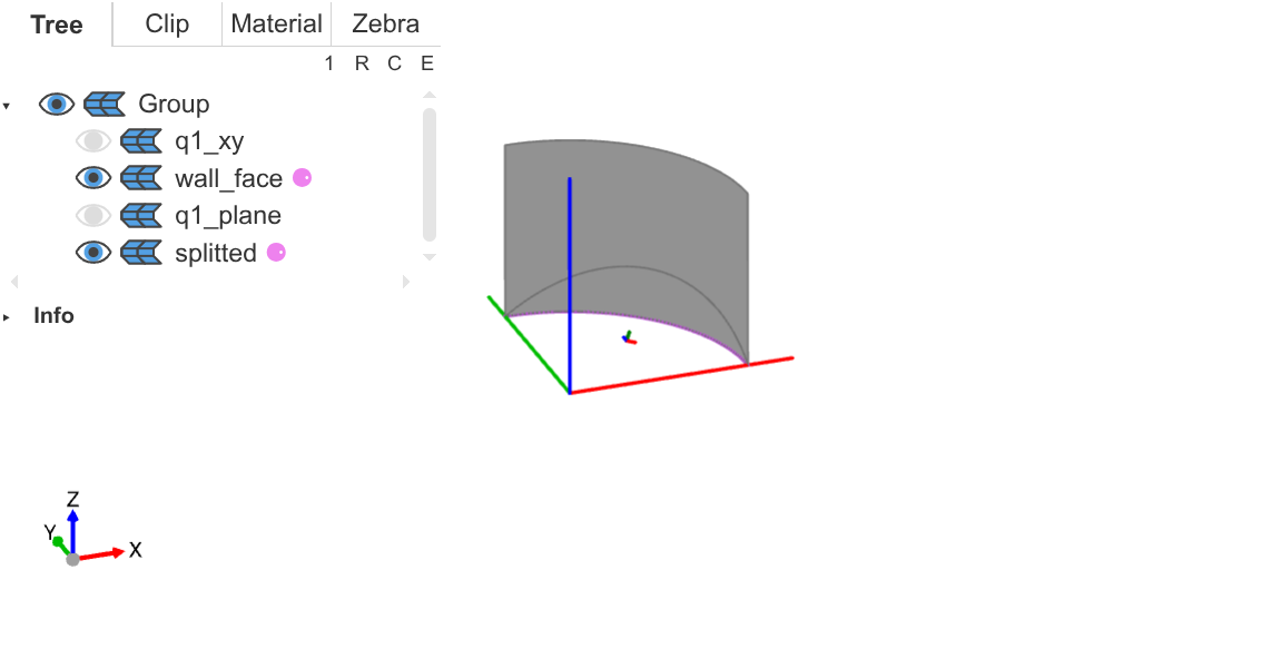
Cut arc face -
Third, only keep this cutting line, which is the main path in the first quadrant. Since cutting only adds one edge, directly calculating the difference in edges before and after cutting gives this edge.
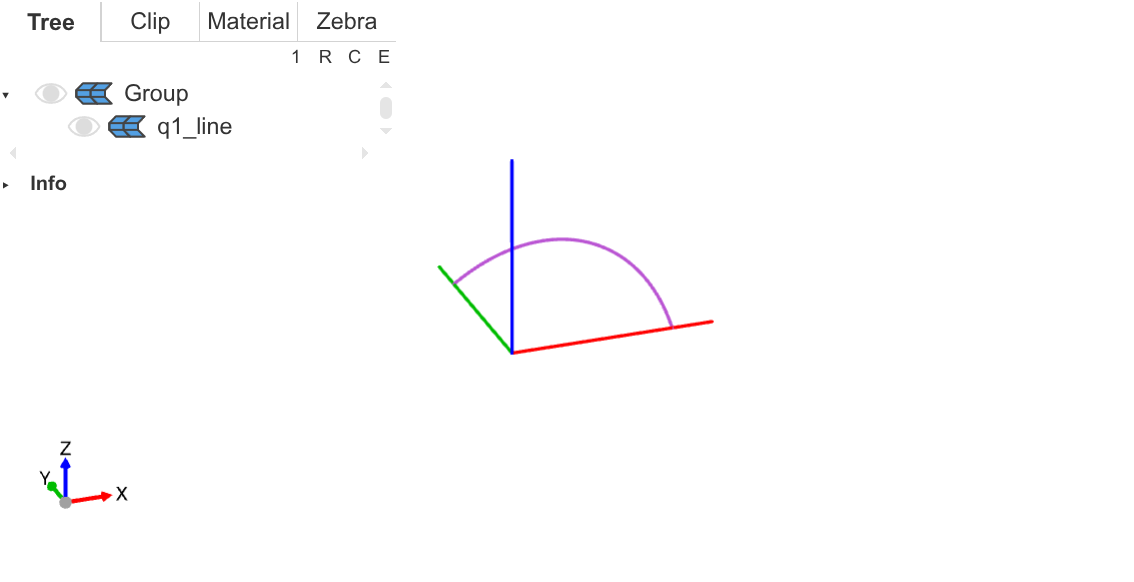
First quadrant main path (oblique view) 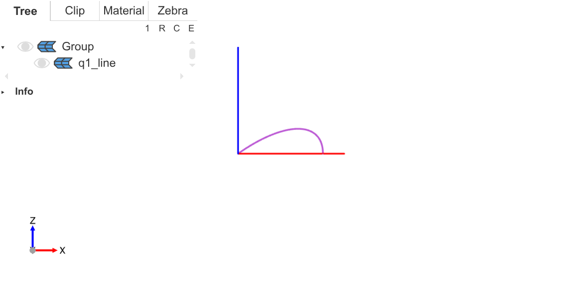
First quadrant main path (front view) As you can see, the front view shows a 1/4 infinity symbol.
⚓ Combining Four Quadrants
Next, through mirroring and rotation operations, assemble a complete circle.
def build_main_path():
    q2_line = mirror(q1_line, Plane.XY).rotate(Axis.Z, 90)
    half_circle = q1_line + q2_line
    return half_circle + half_circle.rotate(Axis.Z, 180)

main_path = build_main_path()-
First step: mirror the first quadrant path downward, then rotate it 90 degrees to the second quadrant, and concatenate into a semicircle.
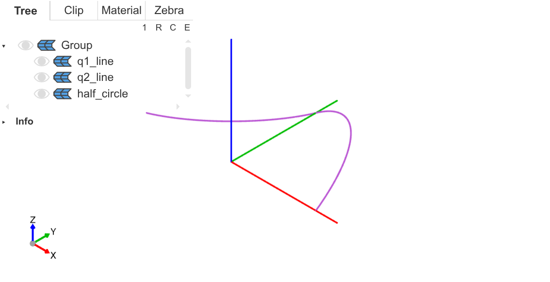
Main path in first and second quadrants -
Second step: rotate this semicircle by 180 degrees and concatenate it to the original semicircle, obtaining the complete main path.
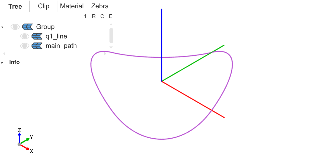
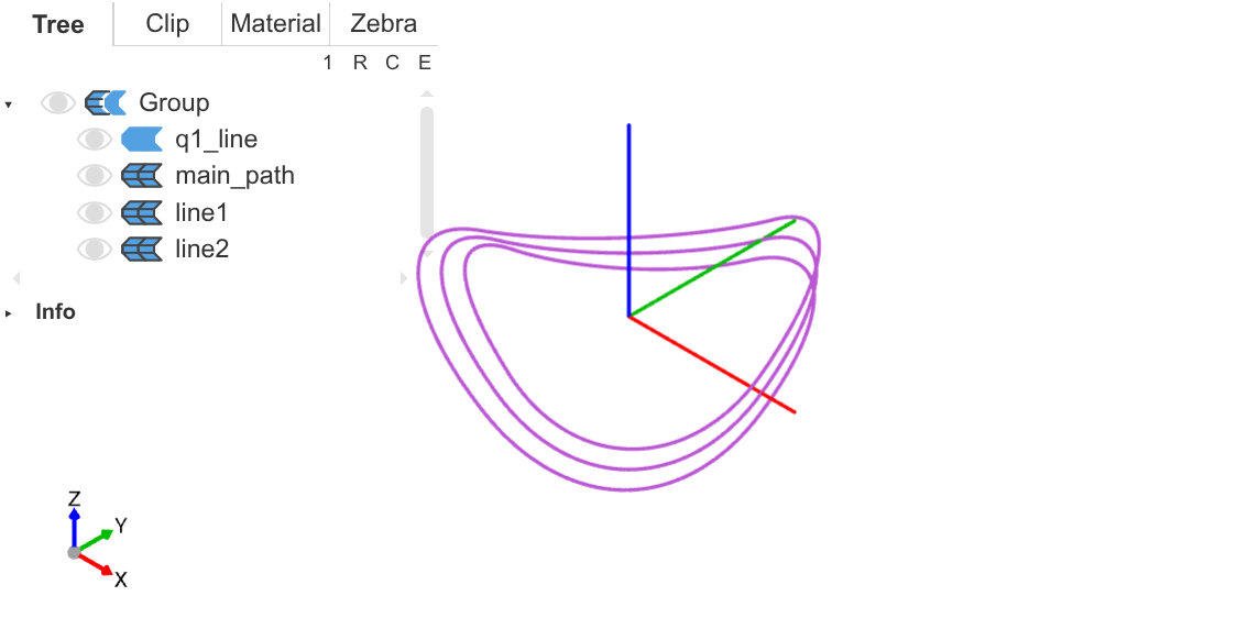
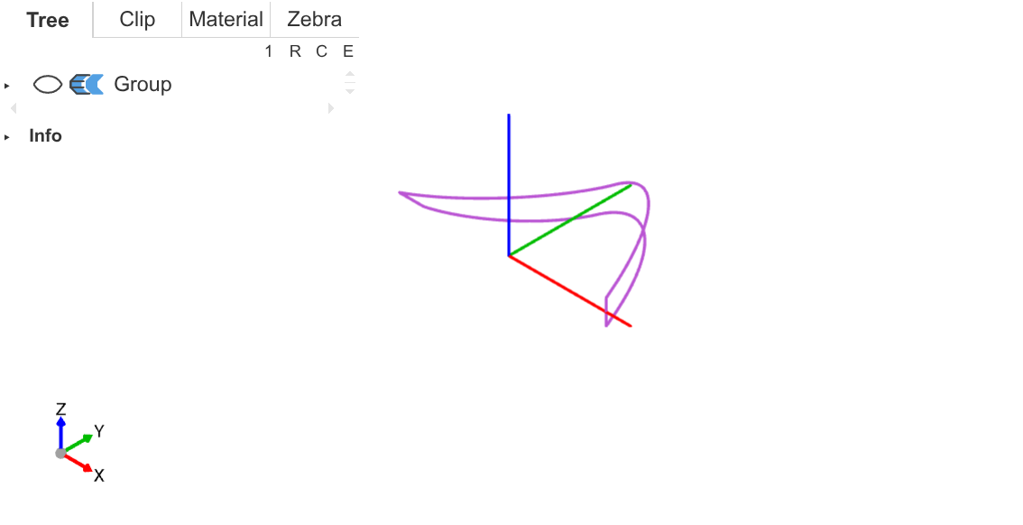
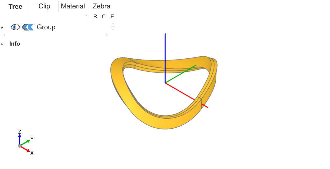
Complete main path (oblique view) 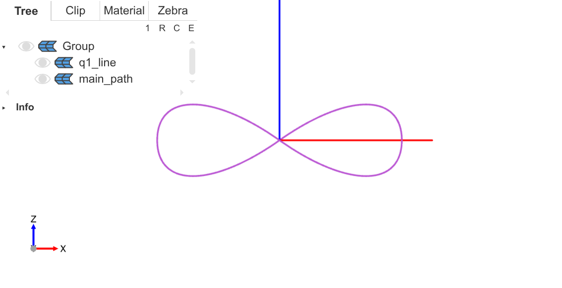
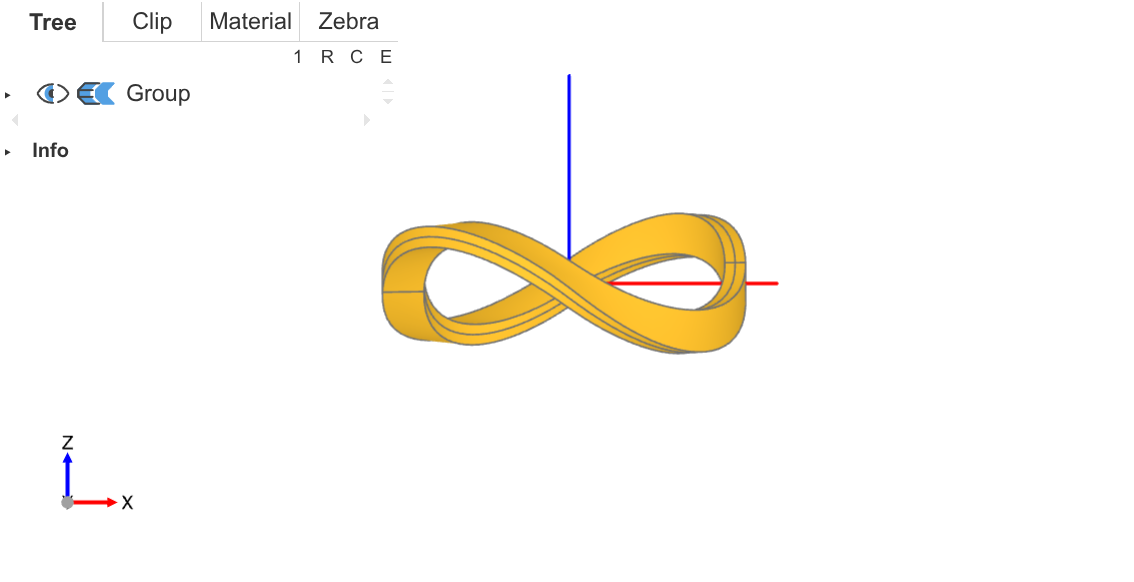
Complete main path (front view) 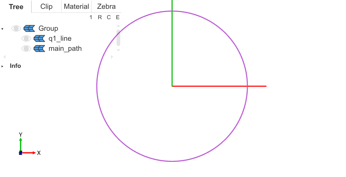
Complete main path (top view) As you can see, the front view shows an infinity symbol, and the top view shows a perfect circle.
⚓ Möbius Strip
Next, I need to model a Möbius strip based on this main path. That is, at each position on the main path, construct a cross-section, and have this cross-section rotate 180 degrees along the main path.
You might think that I can construct a cross-section first, then have this section follow the main path with sweep to directly generate a Möbius strip. Theoretically, this is feasible, but not so in build123d. In build123d, to control the cross-section to rotate 180 degrees, a binormal path needs to be generated as a reference for control. However, since both the main path and binormal path are very irregular, the correspondence between the binormal path generated by the kernel and the main path is incorrect, causing the generated Möbius strip to have width and thickness distortions, which is imperfect.
My approach is:
-
Directly calculate coordinates, use splines to generate the entire strip's boundary line, forming a closed
Wire. -
But due to the special nature of the Möbius strip (I don't know the specific reason), build123d cannot execute
Face.make_surfacefrom thisWireto generate a surface. -
So I split this boundary line into two parts, turning them into two closed
Wires, each of which can be passed intoFace.make_surfaceto generate a face. -
Finally, concatenate these two faces to get a complete Möbius strip surface.
⚓ Boundary Line
I generate this boundary line in two parts, generating half at a time, then merging.
def rotating_spline(begin_angle=0.0, distance=cfg.width / 2.0):
    pts = []
    for i in range(cfg.segments + 1):
        position = main_path @ (i / cfg.segments)
        circle_radian = math.radians(360.0 * i / cfg.segments)
        rotation_radian = begin_angle + circle_radian / 2.0
        radial = position.normalized()
        normal = position.cross(Vector(0, 0, 1))
        up = normal.cross(radial).normalized()
        offset = (radial * math.cos(rotation_radian) + up * math.sin(rotation_radian)) * distance
        pts.append((position + offset).center())
    return Spline(pts)

line1 = rotating_spline()
line2 = rotating_spline(math.pi)-
I use splines to generate the boundary line, where each point on the boundary is obtained by offsetting from the main path by an
offsetvector. -
The
offsetis controlled by an anglerotation_radian, which starts frombegin_angleand rotates continuously as the main path progresses, rotating 180 degrees after one full circle. -
Generating one circle at a time, the first circle has
rotation_radianstarting from 0 degrees, the second from 180 degrees, becauserotation_radianchanges by 180 degrees per circle, so the two circles connect end to end.
An interesting point is the reference system for the angle rotation_radian. I set 0 degrees for this angle to the vector from the origin to the main path position, radial. That is, when rotation_radian is 0 degrees, the offset direction is directly radial to the main path. The 90-degree position is set to the up vector, which is coplanar with the Z-axis and radial vector, and perpendicular to radial.
Here, when writing the code, I found that solid geometry and linear algebra were a bit rusty, not knowing how to calculate the up vector. After consulting an LLM, I recalled the concept of normal vectors.
-
To calculate the normal vector of a plane, you can take the cross product of two vectors on the plane to get a third vector perpendicular to both.
-
First, calculate the normal vector
normalof the plane formed by the Z-axis andradial, then take the cross product of the normal vector andradialto get theupvector, which is on that plane and perpendicular toradial. -
Using the right-hand rule twice to make
uppoint upward.
⚓ Strip Surface
I split the two boundary lines line1 and line2 into two parts each, getting four line segments, then concatenate these segments into two closed Wires, execute Face.make_surface for each Wire to generate a non-planar face, and finally concatenate the two faces to get the complete Möbius strip surface.
line11, line12 = line1.split(Plane.XZ, keep=Keep.BOTH)
line21, line22 = line2.split(Plane.XZ, keep=Keep.BOTH)
connect_line1 = Line(line11 @ 0, line21 @ 0)
connect_line2 = Line(line11 @ 1, line21 @ 1)
wire1 = Wire([line11, line21, connect_line1, connect_line2])
wire2 = Wire([line12, line22, connect_line1, connect_line2])
face1 = Face.make_surface(wire1)
face2 = Face.make_surface(wire2)
infinity_face = face1 + face2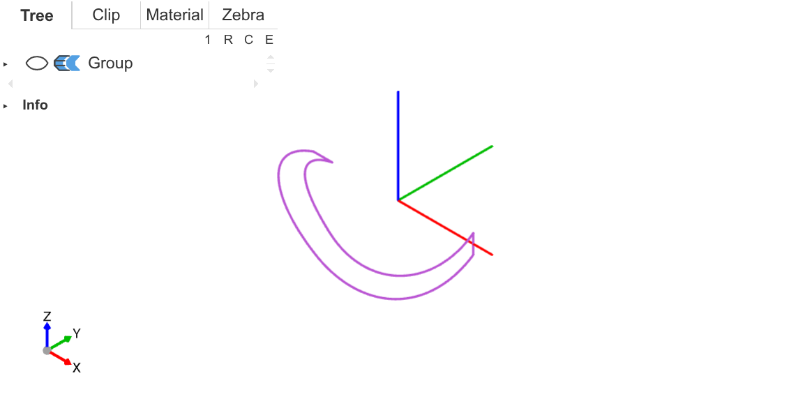
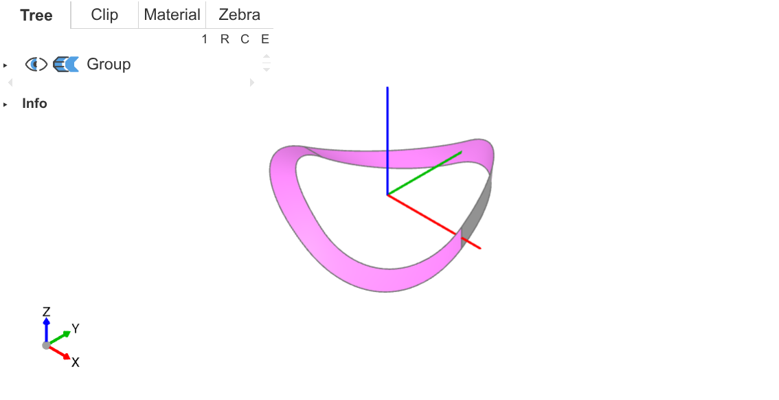
⚓ Volume
Finally, just use the thicken operation to thicken this surface, obtaining a complete volumetric Möbius strip. In build123d, the thicken operation can act on non-planar surfaces.
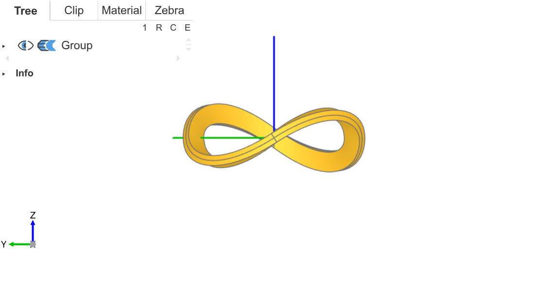
infinity = thicken(infinity_face, cfg.thickness / 2.0, both=True)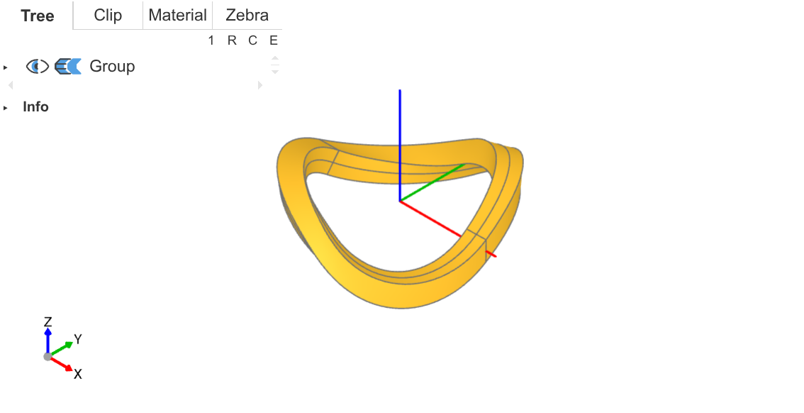
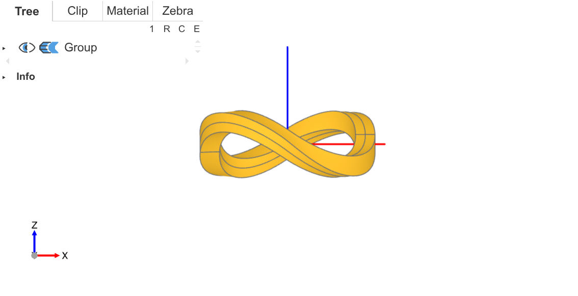
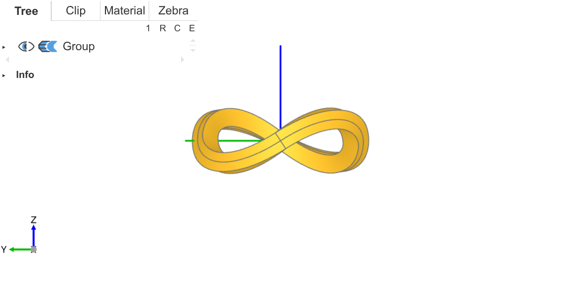
As you can see, the two side views show different twist angles, allowing for different rendering effects.
In the initial parameters I set, thickness equals to width, giving a square cross-section Möbius strip. I also set thickness to half of width, getting a rectangular cross-section Möbius strip.
In the rectangular cross-section version, the front view's left side is slightly smaller than the right, causing visual imbalance. But in the left cross-section, the front part is narrower, so I use a perspective camera to place the narrower part closer (thus appearing larger) to achieve left-right visual symmetry.
⚓ Rendering
Currently, I've only done a basic rendering. Directly import the model into Blender, set up a series of radially hue-gradient light sources starting from the origin, to produce the rainbow effect. I cheated by not trying to make the Möbius strip show rainbow colors through materials (haven't learned yet), but indirectly giving the strip color through light sources.
I used three types of light sources in total:
-
One point light each above and below to illuminate the model's inner side;
-
One area light each above and below to illuminate the model's top and bottom;
-
A cylindrical light source to illuminate the model's outer side.
Placed as follows, all selected (orange) objects are light sources.
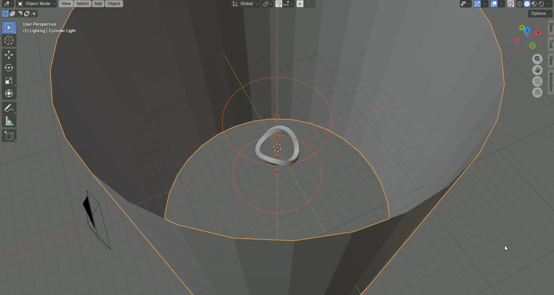
Each light source's configuration is similar, taking the area light as an example. Use coordinates as input to construct a radial gradient texture.
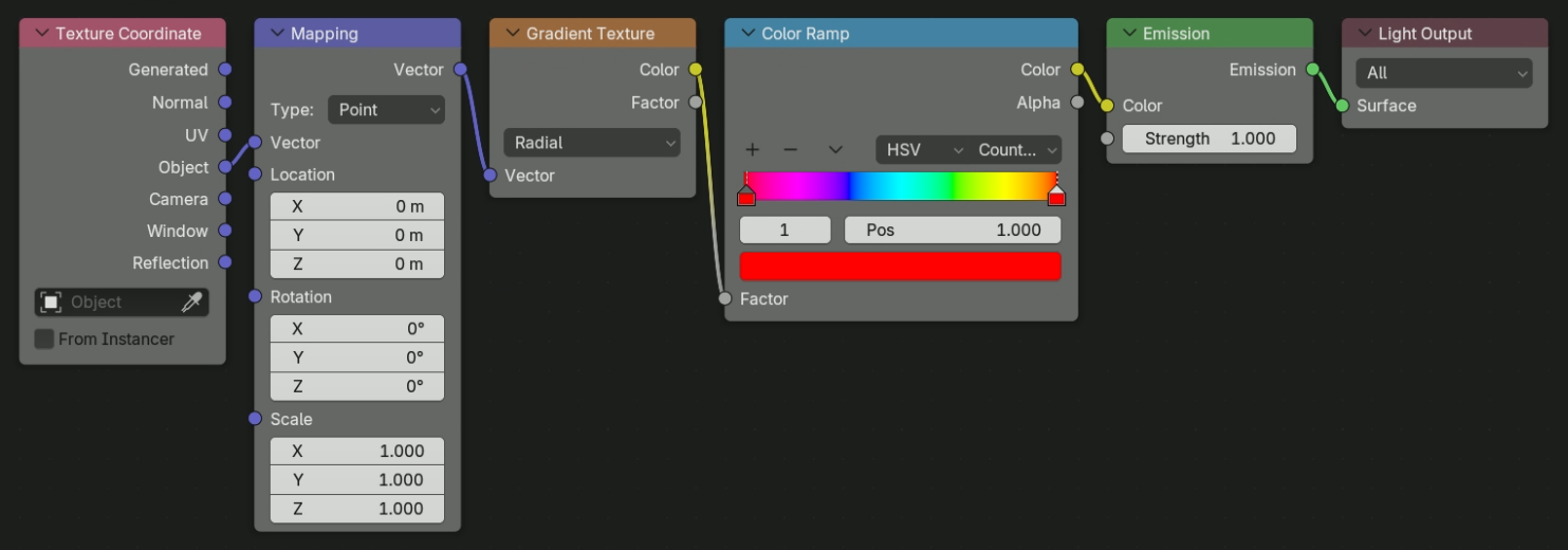
Finally, adjust the camera position, model materials, and color management settings to render the final effect.
⚓ Final Effect
So, in the end, here are the rendering results.